Published on November 11, 2017
Building a Connected Ammeter with Arduino
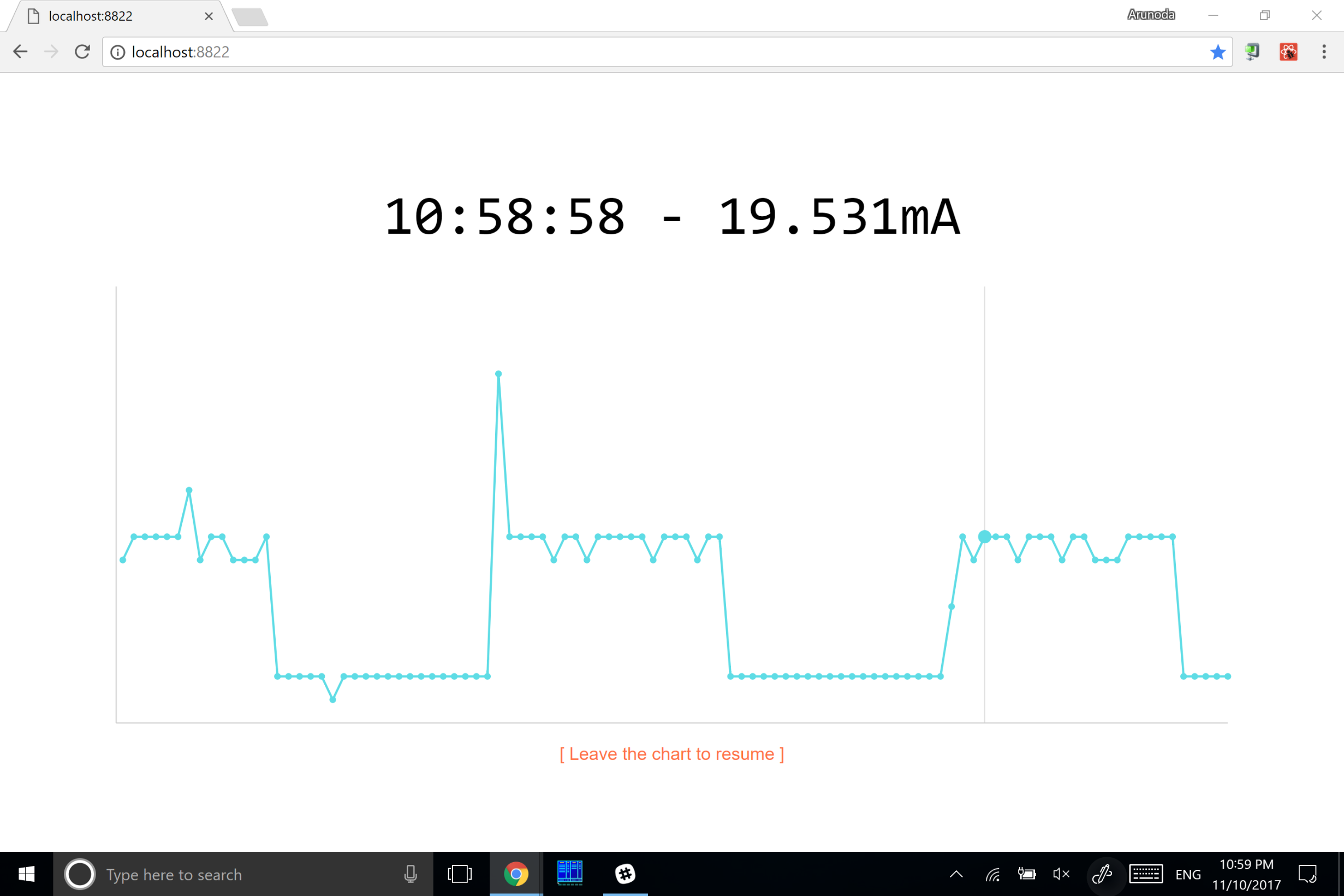
As I continue my electronic experiments, I wanted to measure the current used by ESP8266 at its different stages. I didn’t wanna just look at numbers, but visualize the current via graphs. The current range I wanted to measure is from 120mA to 30uA. At the end, I wanted a graph like this:
Measuring the voltage with Arduino
Arduino has a set of pins which we can use to measure the voltage. We can measure up to 5V in a range of 1024 values. Therefore, the voltage resolution is basically around 5 mv (5000mv/1024).
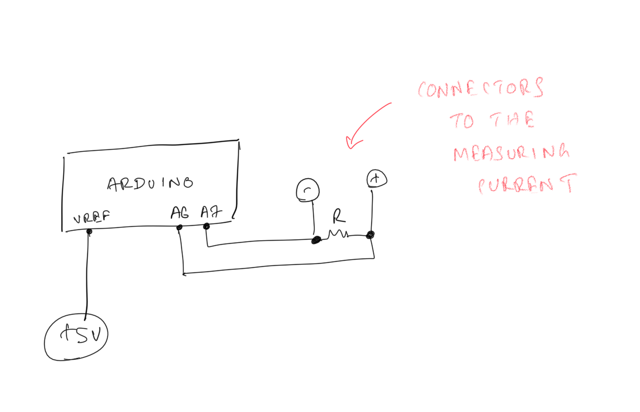
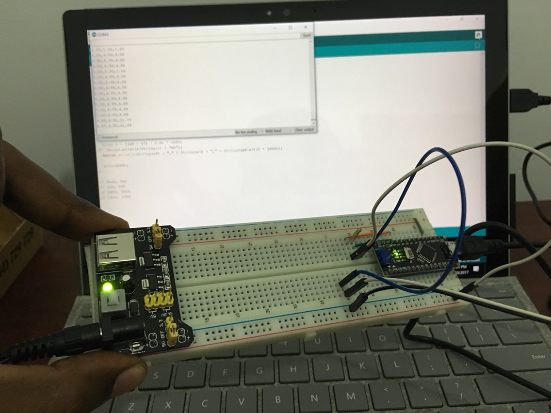
This is my Arduino setup:
Here's the code:
Basically, I'm measuring the voltage between the resistor and applying I=V/R to calculate the current.
It works well. Initially, the accuracy was not that precise. However, I was able to bump up the accuracy by attaching a 5v connection to the AREF pin in Arduino. With that, we can tell Arduino to use that voltage as the reference for analogRead.
Dashboard
As you've noticed in the above Arduino code, I sent measurements to the serial port every 250ms. Then I wrote a simple Next.js app to visualize those measurements.
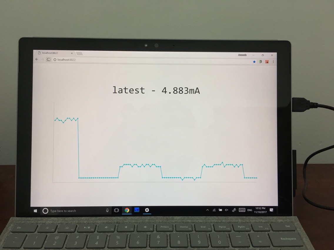
It's pretty simple and it achieves what I want.
Actual Usage
Next, I started using my new ammeter to monitor the current usage of ESP8266. Here's my setup:
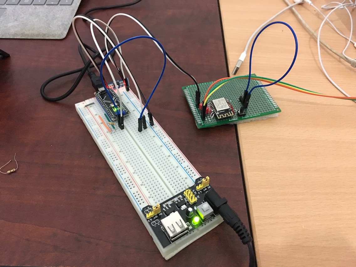
Initially, it failed. I used a 100ohms resistor, where I could measure as low as 50uA of current. I came up with that number by applying I=V/R and using V as 5mv (which is the minimal voltage Arduino can measure).
But it didn't work well.
The reason is ESP8266 didn't get enough voltage to power it up. It needs exactly 3.3v. I used a voltage regulator, but the input to that was 5v. The 100ohms resistor takes a considerable amount of voltage. Hence, the input voltage to the 3.3v voltage regulator was less than 3.3v.
I could have used a higher input of voltage like 12v and give it a try, but I didn't have a good 12v input source (or I was lazy to find one).
Making it Work
I then used a 2ohms resistor and got it working. Then the minimal current I could measure was around 2.5 mA. That was not good enough for me.
In the End
Basically, Arduino is effective at measuring voltage. But it's not good for measuring very low ranges of current.
However, I was able to get an idea of the current usage of ESP8266 and that's good enough for me (at least for now).
My original idea was to build a connected ammeter with some pretty dashboards. But since I can't measure very low current, I am not continuing this project. Nevertheless, this was a very nice experiment and I learnt a lot.
Next Step
As you already know, high precision ammeters are very expensive. But I found a cheap ammeter which is good enough in my case.
After I got it, I'd like to test it and connect it my Next.js powered dashboard. Let’s hope it’ll work well.